


Join the most reactive Vida/Vdash support group on FACEBOOK CLICK HERE
Volvo P2 petrol fuel pumps (Focusing on R / 2.4 T5) though 99% of this is accurate for single pump setups in terms of operation.
The P2r / T5 fuel pump setup is really interesting. It’s return-less but has a return. The lift pump is on the opposite side to where the lifting is done. The lifting is done by a venturi, not actually the lift pump. Crazy .
When replacing the WHOLE in tank pump unit, life is reasonably straight forward.
Have as little fuel in your tank as possible, make sure you tie a line onto the left side pickup so you can pull it back through on replacement, otherwise you have to nearly get in the tank with it to feed the pickup through to the left side. Not much fun.
Facelift R and 2.4 t5 share the same pump setup. Preface lift R is a bit different in terms of electrical connections, but principally they are the same.
How it all works :-
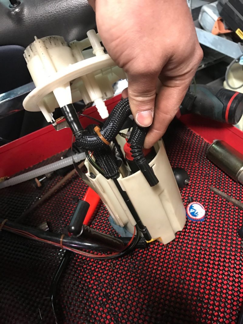
The Swirl pot (white basket) has a one way valve in it at the bottom (orange IIRC) so that when it is submerged in fuel it fills, but if it is lifted out of fuel, it does not empty. This is important for hard cornering. Hard right cornering with an empty tank would cause starvation if it were not for the lift pump keeping the swirl pot full.
The “Lift” pump is on a permanent 12v feed from the CEM (Same power wire that gives the PEM power) and its speed does not change. Its job is to get fuel from the left side of the tank and dump it into the swirl pot.
It does this using a venturi pump. It pushes a low flow but high-pressure fuel FROM THE SWIRL POT – yes…out of the swirl pot lol to the venturi which then turns that low flow high pressure into a high flow but low pressure return into the swirl pot to keep it full. The venturi (white round thing) can get blocked with grit etc which stops the lift pump from working.
The lift pump pushes fuel out of its top, through a bendy pipe to a hard pipe clipped into the side of the white basket, this then goes down to the bottom and out to the venturi on the left side. The Venturi and left side level sender are held in place from the top of the tank. Fuel returns from the venturi on the left to be dumped into the swirl pot to keep the main pump supplied with fuel.
The “Main” Pump sucks fuel up from a strainer at the bottom and pushes it out through the top to the fuel filter and then onto the rail.
The main pump is PWM speed controlled by the PEM according to the demands of the ECU to maintain the pressure desired. Because there is a one-way valve in the fuel pump to stop the system depressurising between use, there has to be a system to deal with rapid changes in pressure and the inertia of the spinning pump motor. This is where we have a return in the return less system. Just before the fuel filter the fuel pipe splits of and goes back to the top hat through a pressure regulator that dumps back down into the swirl pot.
It is vital for correct operation that the venturi is working and dumping back into the swirl pot and that the main pump “return” is positioned correctly so that it dumps into the swirl pot also.
If you are replacing the entire in tank unit, just take your time and you don’t have to worry about the position of these pipes, it SHOULD all be correct out of the box. Just don’t kink the venturi hard lines.
However if you are upgrading the main pump (use a Dw300c 9-1000 it is a 100% perfect drop in and much better than the aero motive stealth / Quantum equivalents which are the wrong diameter, have the wrong outlet and the wrong power connector and require more amps then the DW. Walbro GSS342 is a good replacement too but not a particularly high-performance replacement and a bit wide).
Whilst the black pump basket can be removed separately from the white swirl pot, leaving the white swirl pot and pipes “in-tank” , its honestly easier to get the whole lot out to work on.
The factory heat shrunk corrugated pipe form the top of the pump to the top hat is a 220mm x8mm ID pipe and the existing will usually need to be cut off from the barbed outlets and replacement can be purchased from Fuel performance as well as many other locations .
In order for the pump not to leak (and hold pressure in the system between starts) the flexi pipe must be very securely attached to the top hat and the pump. I recommend using (11mm?) oetiker clamps. Jubilee / Worm drive pipe clips do not provide even pressure and should not be used.
Don’t worry about the spare ground lead when fitting a uprated pimp.. Just keep it out of the way or snip it.
Some useful to know bits no bobs…….
Idle pressure is 400kpa at the Sensor or 300 kpa at the rail.
Ideal idle pump duty in Vida is around 35%
maximum pressure under full load is 560kpa (P2r)
Pump duty actually maxes out at 85% so, if you are getting close to 85% your actually out of pump duty.